AI6YM.radio
Minimum Viable Yagi
Minimum Viable Yagi
Couldn't load pickup availability
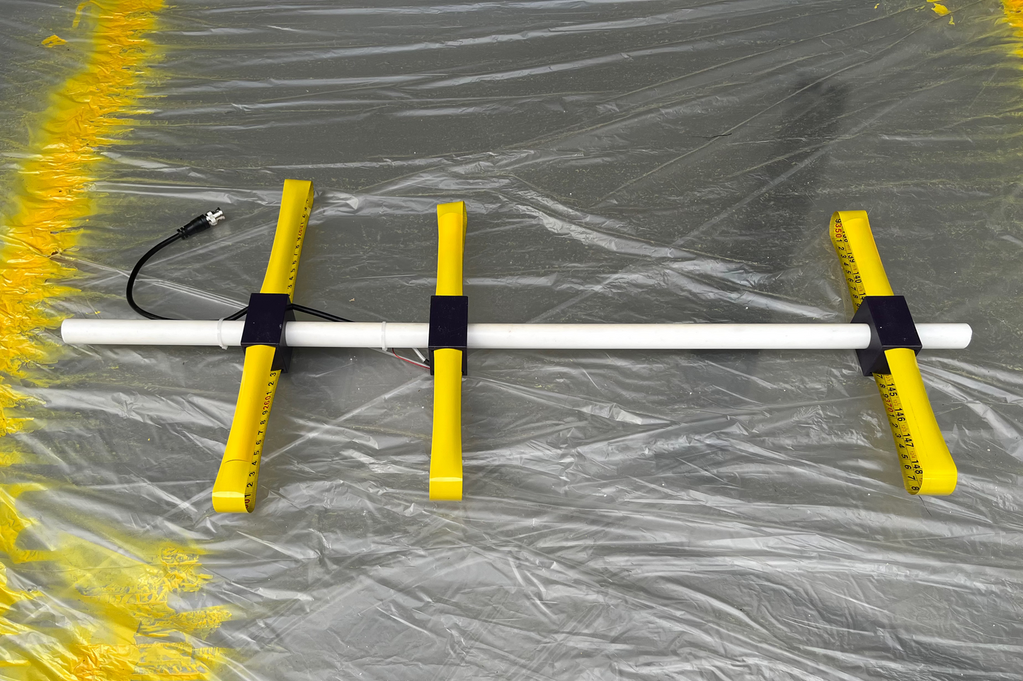
The time honored tape measure Yagi(-Uda) antenna now in kit form! This kit includes precut and finished tape measure elements, 3D printed mounting blocks, a hairpin match wire, BNC terminated coax pigtail, and all the hardware required to build your antenna. You supply a piece of 1/2" PVC pipe and the whole thing goes together with just a #2 Phillips screwdriver.
The 3D printed blocks mean you don't need to cut multiple pieces of pipe or use fittings and hose clamps. The blocks slide onto the pipe and are secured with screws. Elements slide into the blocks and are secured with more screws, and that's it! Impedance match can be tuned by adjusting the hairpin match, and the resonant frequency can be adjusted by moving the driven element block along the pipe.
Source materials on my GitHub, free for non-commercial use.
Build Instructions

First identify your parts. You should have:
- Three plastic blocks - two for parasitic elements and one for the driven element (this one has text on one side).
- Four tape measure elements - two short driven element halves, one reflector (the longest piece) and one director (a few inches shorter than the reflector). Be careful unfolding the elements! The edges can be sharp and the bundle is under spring tension.
- One match element - a short piece of wire with ring terminals on each end.
- One coax pigtail - a coaxial cable with a BNC termination on one end and ring terminals on the other.
- Ten screws in a small bag.
- Two zip ties.
You supply the final piece - a length of 1/2" Schedule 40 PVC pipe. A length around 30" is recommended. You will also need a #2 Phillips screwdriver. A permanent marker and a tape measure would be helpful but you can assemble the antenna without them.
Place the Blocks

You will be making measurements from one end of the pipe - the forward end, ie the end which you point the antenna. The other end of the pipe will be the handle. Make all measurements from the forward end of the pipe to the middle of the blocks. The screw holes on the blocks are in the middle.
Place one of the parasitic element blocks on the pipe 2.5" from the forward end. Make the measurement at the middle of the block (ie at one of the screw holes). On the short side of the block you will see large holes for screws. Insert and tighten a screw on each side to secure the block to the pipe. Do not over tighten the screws!

Note that the parasitic blocks have a small screw hole on one of the long sides. The driven element block has two screw holes on one long side with notches that are used for cables later. You'll want the screw holes on all three blocks facing the same direction.

Place the driven element block on the pipe 17" from the forward end. Make sure the screw holes on the long side of this block are facing the same direction as the first block. Note the notches that are used for cables later - these should point toward the handle end of the pipe. Secure the driven element block with screws through the short sides.
Pro tip: Before tightening the screws press the blocks against a flat surface to align them.
Place the final block on the pipe 23" from the forward end. Make sure the screw hole in this block is facing the same direction as the holes in the other two blocks. Secure the block with screws through the short sides.
If you do not have a tape measure handy use the antenna elements as a tape measure. You will need to do a bit of arithmetic to make your measurements but it'll work in a pinch.
Install Parasitic Elements
Parasitic elements are installed on the two blocks at the ends of the pipe. Each block has two slots (one on each side) you install the elements through the notch on the side which has a screw hole.
Fold the reflector element (the longest element) in half and mark the back side of it with permanent marker at the midpoint. Slide this element through the block on the handle end of the pipe until you can see the mark on the tape through the screw hole. Insert a screw into the hole and tighten it down. The screw will punch through the tape. Do not over tighten the screw!

Install the director (the next longest element) in the same way in the block at the forward end of the pipe.
If you do not have a permanent marker handy you can slide an element into a block and then fold it in half to find the center.
Install the Driven Element Halves
Driven element halves are installed in the middle block. A single screw secures the element and makes the electrical connections. Each element half will be sanded down to bare metal on one end - this is the end that is inserted into the block.
Take one element half and insert the end that has been sanded to bare metal into the block. Like the parasitic element blocks the driven block has screw holes on one side but not the other. Install the element half on the side with the screw holes.

Take one screw and insert it through one ring terminal on the match element and one ring terminal on the coax pigtail. Press this screw on the tape over the screw hole and tighten down. The screw will punch through the tape and tighten into the plastic underneath. Tighten all the way down but do not over tighten the screw!

Arrange the ring terminals, coax, and match element so they fit into the notch in the block. The match element should be on top with the coax underneath (closer to the pipe).
Insert the second element half into the other side of the block. Insert the last screw first through the remaining ring terminal of the match element, then the remaining ring terminal of the coax pigtail, and finally press it into the tape and tighten down.

Finish Up
Bend the match element into a U shape. Use a zip tie to secure the coax cable to the pipe near the driven element block. Use the second zip tie to secure the coax cable again on the handle end.

Built following these instructions your antenna should be a good match across the 2M amateur band. Checking and tuning with a VNA is recommended but not strictly necessary.
You can tune the antenna's impedance match by adjusting the match element. A wider U shape creates more inductance, a tighter shape creates more capacitance. When measuring the antenna with a VNA be sure to hold it away from your body, away from the ground, and away from any metal objects.
The resonant frequency of the antenna can be adjusted by moving the driven element block. Slightly loosen the screws securing the block to the pipe (the screws on the short sides). Slide toward the reflector (handle end) to lower the resonant frequency or toward the director to raise the resonant frequency.
Closing Note
These instructions were created hastily in preparation for Pacificon, better instructions with pictures are coming soon. Feedback on the kit and the instructions is greatly appreciated - email justin@ai6ym.radio.